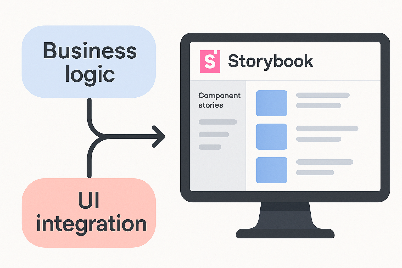
Modern web development thrives on clarity, collaboration, and documentation. As applications grow more complex, it becomes crucial to ensure that everyone—from designers to developers to stakeholders—shares a clear understanding of both the business logic and the user interface. One powerful way to achieve this is by integrating business logic flow diagrams directly with your Storybook stories.
Why Integrate Flow Diagrams with Storybook?
- Unified Documentation: Developers and designers can see not just how a component looks, but also how it behaves and why.
- Faster Onboarding: New team members quickly grasp both UI states and underlying logic.
- Reduced Miscommunication: Visual flows clarify requirements and edge cases, minimizing costly misunderstandings.
Step-by-Step Process
1. Separate Business Logic from UI
Start by ensuring your components are modular. Keep business logic in hooks or controllers, and UI in presentational components. This separation makes documentation and testing much easier.
2. Visualize Business Logic with Flow Diagrams
Use tools like Mermaid (which supports Markdown-based diagrams) or design platforms like Figma to create clear, up-to-date flowcharts. These diagrams should map out decision points, data flows, and error handling.
3. Embed Flow Diagrams in Storybook
Storybook supports MDX, allowing you to embed diagrams right alongside your stories. For example, with Mermaid:
import { Mermaid } from 'mdx-mermaid/Mermaid';

<Mermaid name="business-logic-flow">
flowchart TD
    Start --> ValidateInput
    ValidateInput -->|Valid| ProcessData
    ValidateInput -->|Invalid| ShowError
    ProcessData --> End
</Mermaid>
This ensures the logic is always visible when viewing or testing the component.
4. Link Designs and Stories
Use the Storybook Design Addon or the Storybook Connect plugin for Figma to embed design prototypes. Now, anyone reviewing a story can see the flow diagram, the design, and the live component—all in one place.
5. Automate and Document
Standardize your process:
- Every story must have a business logic diagram and a description of how it maps to UI states.
- Reference design files and related stories for context.
- Use Storybook’s auto-generated docs for consistency.
Example: Button Component
Imagine a Button component with validation logic. In its Storybook story, you’d include:
- A Mermaid flowchart showing what happens on click (validation, success, error).
- The UI story with interactive controls.
- An embedded Figma frame showing the button in various states.
Best Practices
- Collocate diagrams, code, and design files for easy access.
- Review diagrams as part of code reviews to catch logic errors early.
- Iterate with your team—diagrams are living documents!
Conclusion
Integrating flow diagrams with Storybook stories transforms your documentation from static to dynamic. It empowers your team to build, review, and iterate on features with a shared understanding—reducing friction and boosting quality.
Whether you’re onboarding new developers, refining business logic, or collaborating with designers, this approach ensures everyone is on the same page, every step of the way.
Featured image: A developer’s workspace with a flowchart and a Storybook UI side by side, symbolizing the integration of logic and design.
No comments:
Post a Comment